Learn to Animate Staging with Guided Tours
Guided tours are an important tool in DPO-Voyager due to their utility and high adaptability. If you haven’t already, we invite you to learn the basics of creating a guided tour via this guide.
Essentially, guided tours serve to provide a narrative framework for an eCorpus scene. The steps are most often used to highlight different viewpoints of the same model, encourage the reading of articles or annotations… However, it is also possible to go further, by animating parts of an object to show how it works, for example.
Summary
- The different mediation possibilities
- What you need to know
- The central parameters to modify
- Approaching guided tour parameters
- Practical Exercise
The different mediation possibilities offered by Guided Tours
Guided tours offer multiple mediation possibilities in a DPO-Voyager scene. Providing the option of a guided tour to your user is a real asset for them, as they will be able to fully benefit from the semantic enrichment provided.
A good so-called “basic” guided tour therefore aims to show its content in an interesting and thoughtful way, so as to link it to certain viewpoints of its model. For example: planning a step showing a zoom on a character’s head and linking an article related to that element.
A so-called **“animated” guided tour focuses here on the staging and evolving scenography of the subjects, in order to put them in motion. They can very well be exempt from any annotation or article, although these are highly recommended to fully appreciate the movement demonstrated via this functionality.
Examples of staging
These animations can be used for demonstration of movement, or fragmentation to show the internal structure of a mechanism. Here is a non-exhaustive list of different presentations allowed by guided tours:
-
Show how the internal structure of an object is assembled:
-
Show a hypothesis of fragment reconstruction:
-
Show the internal workings of a mechanism:
What you need to know
A little more explanation on translations
This animation effect is possible thanks to the translations of parameters (position, rotation, etc…) of objects from one step to another, aided by an assisted transition.
To put it simply, let’s break down the logic behind creating steps and the transitions provided by the tool:
- Step A retains information about the position of objects and the viewpoint in space.
- Example: I show the front face of my object
- Step B also retains information about the position of objects and the viewpoint in space, independently of point A.
- Example: I show the back face of my object
The translations of step A and B are different from each other.
We can compare the 3D scene to a photo studio. Step A is a photo taken with the camera placed in front of the object, step B is a photo taken with the camera placed in front of the object: so it is the position of the camera that has moved between these two images.
If guided tours do not look like a photo slideshow, it is thanks to the existence of Transitions, which add automatic interpolations between these translations to create a fluid movement.
Let’s take the photo studio example again to clarify:
-
Step A shows the front of the object while step B shows the back of the object.
-
Between these two steps, we can imagine an actor moving. First in front of the object to show step A, then behind the object to show step B.
- The transition here plays the role of the actor moving from point A to B.
While the example is based on camera movement, it is not the only parameter taken into account in the steps.
We can then imagine guided tours as a puppet theater, where the steps decide the position of the puppets while the transitions would be invisible actors articulating the puppets to animate them between two positions.
Decomposing your model into several parts
As you will have understood, each model can move in the scene according to your needs, while the transitions will take care of animating these movements.
Therefore, translations are made for each model independently, depending on the pivot point assigned to them during their export. (see next point). If each object is limited to a global movement, it is sometimes necessary to decompose it into several parts to obtain the desired movement.
To return to the lock example: each object performing a movement independently of the others has been separated into different GLBs. The four visible springs, for example, constitute four different GLBs, because each spring performs a different movement at a given moment.
For organizational purposes, it is not necessary to decompose all the small parts of a mechanism. Here, the cylinder, the bolt, and the back of the stator (represented in purple) are indeed three different parts, which were nevertheless exported in the same GLB: the three parts have the same translation at the same time (rotation at the time of key turning). It is therefore easier to make a single translation and manage only one GLB than three different GLBs on which the same translation is applied three times.
Special case for Derivatives
Special case: DPO-Voyager manages what are called Derivatives. These are object states that serve to define its quality. A single object in the scene can therefore have several GLBs of different qualities.
These qualities are:
- Highest: Best display quality. Often for “raw” quality models (during 3D scans, for example)
- High: Quality considered HD (High Definition)
- Medium: Medium quality. Geometry remains good quality, textures are of lower quality.
- Low: Low quality. The model still looks good from a distance, but shows deficiencies when zoomed in.
- Ultra Low: Lowest quality. Used when the object is visible from a distance: it maintains a good silhouette and allows good performance.
- AR: For Augmented Reality. Used to apply the Augmented Reality feature to the scene. You can learn more in this guide.
The use of derivatives is very common in video games or web display, as they allow for modifying the LoD (Level of Detail) based on user hardware capabilities, for example.
To put it simply: each model implemented as a Derivative will be loaded as soon as the eCorpus scene is launched: so be careful not to overdo the size of your models, even in Highest quality. The quality of the displayed model will be decided based on the capabilities of the device used so that the 3D viewing remains fluid in all circumstances.
While derivatives can be useful, they are not always used. However, they can still serve for comparisons in guided tours.
This is the case, for example, with this scene: it presents only one object, containing two different GLBs: one GLB representing the structured light scan in the High derivative (which must be as precise as possible for research), and one GLB representing the photogrammetry scan in the Normal derivative (which can be lightened to still be visible with lower performance).
The two versions are compared during the guided tour.
How to properly position an object’s pivot point
As seen previously, it is important to know where to place your pivot point to allow for proper translation. A pivot point, as its name suggests, determines the center of the axis on which your object will pivot/rotate.
For example, a lever will have its pivot point at its base, while a door will have its pivot point on its side.
Pivot points can be changed directly on the GLB file via a modeling application, such as Blender. However, they are automatically recalculated based on their location in the DPO-Voyager scene.
Note the difference between the object’s “local” pivot point, which influences the translation parameters in the Pose tab, and the object’s “global” pivot point, which is defined by its orientation and position in the Pose tab.
How to correctly reposition your object’s pivot point
The pivot point of an object imported into eCorpus is automatically set according to its original placement in the DPO-Voyager scene: its pivot point will always be placed at the strict center of the scene.
Consequently, centering an object in the center of the scene in its initial configuration will automatically define its pivot point at the center of the object.
Note this configuration change is made only in the “Pose” tab of DPO-Voyager’s Edit mode. You can learn more about this tool in this guide.
Tip If you wish to reposition the pivot point on your object without changing its location in the scene, you can “compensate” for the modifications made by the Pose changes by editing the Position Parameters of your object.
Example: If you move your object by 0.5 on an axis in the Pose tab, add the inverse value, here -0.5, in the correct axis of the object’s Parameter tab.
-
If you want to improve your object’s rotation, make sure to change its position relative to the center of the scene.
-
If you want to improve your object’s movement, make sure to change its rotation relative to the viewpoints of the scene. (having an object oriented on a single axis allows for simpler translation than with an object oriented between two axes)
Tips It is important to check the pivot points of your objects before creating any guided tour. Indeed, the translation values of the steps will remain the same as saved. A change in the pivot point may therefore lead to incorrect translations.
Reminder regarding scene saving
It is important to remember that saving the scene during a guided tour will also save the current translations in the scene’s default display. That is: if you save the scene during a guided tour while the object has a particular position and movement, it will retain that position when the scene is refreshed, even when the guided tour is not active.
If this happens and you wish to revert to the object’s base state, you will need to manually modify the object’s translation values and save the scene again, or restore an older version in the eCorpus History.
Tip: it seems important to keep a step in your guided tour where the object remains in a neutral, default position. Thus, if a problem as described above occurs, you just need to go to this step where the object’s position is neutral then save the scene again.
It is therefore important to remember to exit your guided tour (by completing all steps, and by clicking again on the “guided tour” icon) before saving your scene.
Small note to remember that annotations are done by 3D models and that sometimes they need to be redone??? (test creating null objects to have “floating” annotations and see if it changes anything)
An important point to consider in these animations are annotations. If you have already read the annotations guide you know that each annotation is linked to a 3D model. Consequently, they follow the translations of these models.
If, for any reason, you wish to change the appearance of your object, while keeping its linked annotation, or keep a fixed annotation in space that does not move, we can offer you these few tips:
-
One object, two different derivatives: an annotation cannot be linked to more than one object. However, an object can contain several GLB 3D models thanks to its derivative system. It is therefore technically possible to have up to 4 different 3D model forms via this system. * Two different objects, two similar annotations: without having to touch an object’s parameters, the most direct solution is to create an additional annotation, this time on the second desired object. Caution: this method is not recommended because it involves making any changes to an annotation multiple times.
-
An annotation fixed on an invisible object: this method is inspired by the Null (or Empty) Controllers found in computer graphics. It consists of creating a “container” object that will host the annotation, and can be placed in the scene as you wish. Then, deactivate the object’s visual in its Parameters by setting the Visible indicator to Off. Annotations, as long as they are active in the scene, will remain visible, even if the object is not.
The central parameters to modify
Translations based on the rotation and position of objects form a good basis for staging a Guided Tour. To go further, it is also possible to change other parameters, such as an object’s visibility between two steps, for example.
These appearances and other parameter changes are not necessarily animatable by default. It is important to activate their state changes via other parameters listed in this section.
What is a Tag?
Tags are a practical classification system that allows for sorting the appearance and disappearance of certain visible information. Caution: DPO-Voyager scene Tags should not be confused with eCorpus Collection Tags.
Scene Tags are closely linked to Annotations, as it is in this tab that they are visible. If you wish to learn more about Annotations, please refer to this guide.
However annotations are not the only tools that can benefit from sorting by Tag: objects can too. The system and storage location of this data remain the same, although the parameters are in two different places.
Object Tags are particularly useful for managing the appearance and disappearance of multiple 3D models. They become indispensable when you want to show complex groupings, such as frameworks or machine mechanisms.
Annotation Tags
If you have followed the Annotations guide, you should know that they can be activated or deactivated in the scene via the Annotations icon on the left of the Explorer.
This state is animatable in guided tours, which can be very practical to avoid overloading the scene with information. However, its drawback is that it deactivates all annotations, without any distinction.
Thanks to the Tag system, it becomes possible to classify annotations, to make them appear or disappear independently of other tags.
By default, annotations do not have Tags when they are created. The container provided to receive this information is empty.
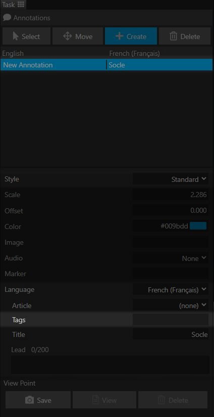
To add Tags, no particular creation step is needed. Select the desired annotation and write the name of your chosen Tag in the container provided for this purpose.
You will notice the appearance of this Tag in a small pane at the bottom of the Explorer, as shown in the example below.
Warning the name of a Tag constitutes an annotation category to be displayed visible by all viewers of the scene. Therefore, please ensure that this name best reflects the category it represents.
To display a Tag, locate its name in the Tag pane and click on it. The name will be outlined in blue to show its activation, and the linked annotations will be displayed. The process is the same to stop the display of these annotations.
To add other annotations to this Tag, write the same name in the Tag parameter of the desired annotations. Be careful to avoid typos: if a Tag name is not strictly identical to an already existing Tag, a new Tag will be created.
To delete a Tag, replace or delete its name in all linked annotations.
Annotations without a Tag always remain visible as long as global Annotations remain activated.
3D Model Tags
In the same way as Annotations, 3D models can be grouped under different Tags.
By selecting the desired object, you can access its Tag value via the “Parameters” tab at the top of the Explorer.
The process is the same: by writing the name of your chosen Tag in the container provided for this purpose, a Tag category will be created and displayed in the pane provided for this purpose in the Annotation tab.
By doing so, both 3D Model Tags and annotation tags are treated in the same way. It is therefore possible to combine Annotations and 3D Models under the same Tag
To add other annotations to this Tag, write the same name in the Tag parameter of the desired annotations. Be careful to avoid typos: if a Tag name is not strictly identical to an already existing Tag, a new Tag will be created.
To delete a Tag, replace or delete its name in all linked annotations.
Thanks to this system, it is therefore possible to make several 3D models appear or disappear with a single click in a simple and organized way.
Approaching guided tour parameters
In order to simplify the creation of Guided Tour steps, not all features that can be taken into account in their animation are activated by default. For example, if you wish to change the color of your model from one step to another, you will first need to activate the corresponding function in the guided tour parameters.

These Parameters are available in the “Tours” tab at the top of the Explorer. In the lower left, in the list of created guided tours, a series of icons is available.
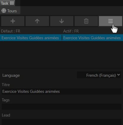
The guided tour parameters icon is represented by three horizontal bars, on the far right of the line.

You will notice that three icons are already active in this list: Reader, Viewer, and Navigation. It is not recommended to deactivate them to avoid creating errors in the application.
They correspond to the data to be taken into account when creating guided tour steps. For example, the “Models” parameter allows the steps to store data from 3D model parameters, such as their visibility or material properties.
Warning: not all parameters of a functionality are animatable. If you have questions about how to animate your object, or if you wish to implement an animatable parameter, do not hesitate to contact us via contact@ecorpus.eu
Animating object parameters
| Category | Name | Description | Associated guided tour parameter |
|---|---|---|---|
| Transform | Transform | Allows you to modify the model’s translations (position, rotation, and scale) | Animatable by default |
| Model | Quality | Allows you to change the Derivative of your model. Changes the model based on the quality chosen during its import | Models |
| Object | Visible | Allows you to make your object appear or disappear | Models |
| Material | Override | Decides whether the changes defined in these parameters are visible or not | Models |
| Slicer Enabled | Decides whether the object is affected by the Cut Tool | Models | |
| Base Color | Adds a definable tint to your model’s texture by multiplication | Models | |
| Opacity | Defines your model’s transparency (only visible with a Default Shader) | Models | |
| Roughness | Defines your model’s shininess (a low value defines a shiny object) | Models | |
| Metalness | Defines whether the object reflects its environment (a value of 100 is equivalent to a metallic object) | Models | |
| Occlusion | Defines the intensity of Ambient Occlusion (Artificially accentuates shadows in the model’s corners and crevices.) | Models |
To learn more about Guided Tour parameters
In the same way as Object parameters, Tool parameters (Measure, Cut, etc…) are also animatable via these parameters. To learn more, please refer to this guide.
Practical Exercise: learn step-by-step to create the lock scene
As a practical example, here is an exercise that we will explain step-by-step so that you can reproduce it yourself and test the possibilities offered by this Animation principle via Guided Tours.
If you do not yet have an eCorpus base or account, you can still participate in this exercise via a StandAlone scene.
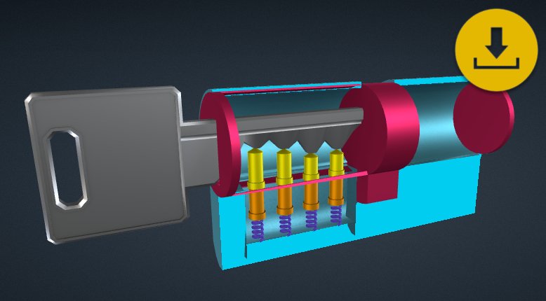
Here’s what the scene looks like once this exercise is complete:
Step 1: Define the fragmentation of your 3D model
First of all, it is essential to clearly define how the subject of the demonstration will be fragmented.
-
My goal: to show how a lock works through the interaction of the key with the internal mechanism.
-
What are the different steps to show?
- General view of the elements;
- The key is inserted into the stator, the mechanisms (pins, counter-pins, and springs) react according to the key’s bitting;
- The key turns, the bolt and pins follow it.
-
From this plan, group the objects by similar translation
- Object that does not move: stator
- Object that rotates and moves in space: key, pins
- Do they have the same movement? No -> The pins and the key will be exported independently
- Object that rotates: bolt, cylinder
- Objects that deform: springs
- Do the objects have the same deformation? No -> Each spring will be exported independently
- Objects that move: counter-pins
- Do the objects have the same movement? No -> Each counter-pin will be exported independently
This kind of reasoning is not simple and requires experience, don’t worry if this part still seems a little unclear to you.
You can download the main 3D models used in this exercise: By clicking here
Step 2: Import your 3D models into the scene
First, we create the scene by importing the Lock_Key.glb object. Be sure to name the scene correctly before creating it. Why not name it “Lock Exercise”, for example?
Warning, the chosen name will be visible in the scene link. It is therefore important to avoid special characters such as spaces “ “. It is common to replace them with hyphens ““._
If you are using the StandAlone scene, you will not need to go through this scene creation step.
Once your scene is created, switch it to edit mode, and drag and drop the rest of the models.
For each model, remember to choose a Derivative quality (preferably High).
-
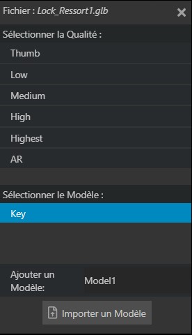
If you want to replace an object in your scene, select the name of the object to replace in this menu.
-
If you want to add a new object to the scene, click on the frame titled “Add a model” and name it so that you can easily recognize it.
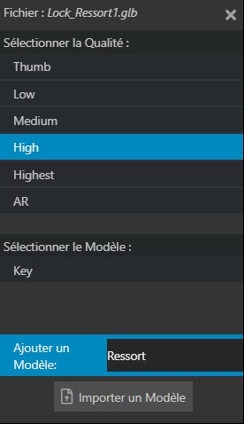
You can then click on “Import a model” to finish importing your model.
At the top of this menu is the name of the file you are trying to import. Following this example image, we are trying to import the Lock_Ressort1.glb file. The chosen quality is High, the “add a model” parameter is selected and named “Ressort” accordingly.
You don’t see your models appearing in the scene? This is normal, we will see in the next point how to solve this problem.
Step 3: Check the Units
Between the export and import of 3D models, it is very common for the measurement units of different 3D applications to be incorrectly recognized. If you don’t see your models: it’s because they are not in the same units of measurement as the first imported model.
To check the measurement units of your model, we will go to the parameters of our objects.

Then select the key, either by clicking on its 3D model in the Explorer, or by clicking on its name in the Navigator.
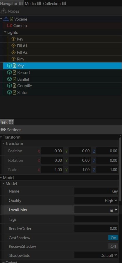
In the object’s parameters, you will find the “Local Units” option. This is the current unit of measurement of the selected object.
Note that the key has measurement units specified in meters (m).
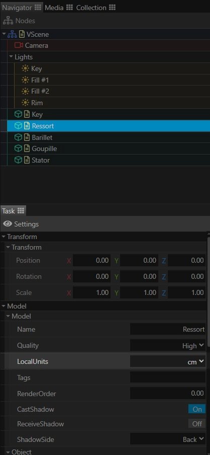
By checking the rest of the objects, we can see that their units of measurement are defined in centimeters (cm).
The objects are therefore visible: they are just so small that they go unnoticed.
It does not seem logical for a key to be measured in meters due to its small size. We will therefore change its LocalUnits to centimeters.
Now, all the objects in the scene are too small. DPO-Voyager scenes have a unit of measurement in meters (m), so it seems logical that objects with centimeter (cm) units of measurement appear small.
If LocalUnits define the unit of measurement of an object, GlobalUnits define the unit of measurement of the scene.

This parameter is located in the Pose tab at the top of the Explorer.
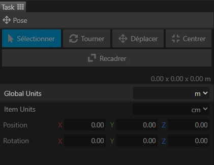
In Global Units, change the units from meters (m) to centimeters (cm). If you haven’t already, you can also take the opportunity to change the object’s units to cm in ItemUnits (parameter just below GlobalUnits).
Step 4: Check Object Parameters and Change their Materials
In this step, we will check, object by object, their parameters, their correct rotation axes, and modify their material to assign them a color.
In the Parameters tab, select each object to ensure they function as you wish. Here are the verification steps to help you:
Stator
First, we check the stator. This part hides the finest pieces, like the pins, so it’s more practical to deal with it first.
- Transform If you remember step 1, the stator does not move, so no verification is necessary at this level.
-
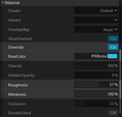
Material These parameters are used to change the visual aspect of the object.
-
Override Check this parameter to On to make the changes visible.
-
BaseColor Click on the white rectangle to change the color of the object. Here, we will make it appear blue.
-
Metalness For practical reasons, we will change the Metalness (also called Metallic) before the Roughness. The stator is made of metal: the Metalness is therefore logically pushed to 100%.
-
Roughness This option will only be used for aesthetics. Lowering this value will make the object shinier.
-
-
Object For now, we will deactivate the Visible parameter to be able to see the other objects in the scene.
Key
Next, we check the key:
-
Transform If you remember step 1, the key moves up and down, left to right, and performs a side rotation that we can call a “rolling” motion. To verify translations, long-press on a value’s container and drag from left to right. The value will then increase or decrease. If the value changes are too abrupt, hold down the “Ctrl” key on your keyboard during the process.
-
The most important movement is when the key enters and exits the Stator. After verification, this movement occurs without problems on the Z-axis.
-
The most important rotation is when the key performs a rolling motion to operate the cylinder. After verification, this movement occurs without problems on the Z-axis.
-
-
Material These parameters are used to change the visual aspect of the object.
-
Override Check this parameter to On to make the changes visible.
-
BaseColor Click on the white rectangle to change the color of the object. Here, we will make it appear grey.
-
Metalness For practical reasons, we will change the Metalness (also called Metallic) before the Roughness. The key is made of metal: the Metalness is therefore logically pushed to 100%.
-
Roughness This option will only be used for aesthetics. Lowering this value will make the object shinier.
-
Cylinder
Next, we check the Cylinder and the Bolt (both in the same object):
-
Transform If you remember step 1, the cylinder does not move, and performs a side rotation that we can call a “rolling” motion. To verify translations, long-press on a value’s container and drag from left to right. The value will then increase or decrease. If the value changes are too abrupt, hold down the “Ctrl” key on your keyboard during the process.
- The most important rotation is when the cylinder performs a rolling motion by key actuation. After verification, this movement occurs without problems on the Z-axis.
-
Material These parameters are used to change the visual aspect of the object.
-
Override Check this parameter to On to make the changes visible.
-
BaseColor Click on the white rectangle to change the color of the object. Here, we will make it appear fuchsia.
-
Metalness For practical reasons, we will change the Metalness (also called Metallic) before the Roughness. The cylinder is made of metal: the Metalness is therefore logically pushed to 100%.
-
Roughness This option will only be used for aesthetics. Lowering this value will make the object shinier.
-
Pins
Next, we check the Pins one by one:
-
Transform If you remember step 1, the pins move up and down, and perform a side rotation that we can call a “rolling” motion. To verify translations, long-press on a value’s container and drag from left to right. The value will then increase or decrease. If the value changes are too abrupt, hold down the “Ctrl” key on your keyboard during the process.
-
The most important movement is when the pin moves up and down depending on whether the key is inserted into the stator or not. After verification, this movement occurs without problems on the Y-axis.
-
The most important rotation is when the pin performs a rolling motion by the action of the key and the cylinder. After verification, this movement occurs without problems on the Z-axis.
-
-
Material These parameters are used to change the visual aspect of the object.
-
Override Check this parameter to On to make the changes visible.
-
BaseColor Click on the white rectangle to change the color of the object. Here, we will make it appear yellow. For the other pins, copy-paste the code in #xxxxxx format to unify their color.
-
Metalness For practical reasons, we will change the Metalness (also called Metallic) before the Roughness. The pin is made of metal: the Metalness is therefore logically pushed to 100%.
-
Roughness This option will only be used for aesthetics. Lowering this value will make the object shinier.
-
Counter-Pins
Next, we check the Counter-Pins one by one:
-
Transform If you remember step 1, the counter-pins move up and down, and do not rotate. To verify translations, long-press on a value’s container and drag from left to right. The value will then increase or decrease. If the value changes are too abrupt, hold down the “Ctrl” key on your keyboard during the process.
- The most important movement is when the counter-pin moves up and down depending on whether the key is inserted into the stator or not. After verification, this movement occurs without problems on the Y-axis.
-
Material These parameters are used to change the visual aspect of the object.
-
Override Check this parameter to On to make the changes visible.
-
BaseColor Click on the white rectangle to change the color of the object. Here, we will make it appear orange. For the other counter-pins, copy-paste the code in #xxxxxx format to unify their color.
-
Metalness For practical reasons, we will change the Metalness (also called Metallic) before the Roughness. The counter-pin is made of metal: the Metalness is therefore logically pushed to 100%.
-
Roughness This option will only be used for aesthetics. Lowering this value will make the object shinier.
-
Springs
Next, we check the Springs one by one:
-
Transform If you remember step 1, the springs do not move, do not rotate, and will perform a scale change on their height to represent the deformation of the spring once actuated. To verify translations, long-press on a value’s container and drag from left to right. The value will then increase or decrease. If the value changes are too abrupt, hold down the “Ctrl” key on your keyboard during the process.
- The most important movement is when the spring deforms in its height, compressing depending on whether the key is inserted into the stator or not. After verification, this movement occurs poorly on the Y-axis.
Solving the deformation problem
We notice that changing the spring’s scale causes it to move: its pivot point is not well positioned in space and consequently leads to errors.
To be as practical as possible, we want the spring to maintain a fixed point at the bottom and deform by extending upwards. Logically, the pivot point should be positioned at the very bottom of the spring.
To learn more about repositioning a pivot point, please refer to this guide.
In the Pose tab, we will reposition each spring so that its lowest part is positioned at the center of the scene (at the intersection of the three colored axes). For better visibility, do not hesitate to make the other objects invisible.
Reminder Once the object is repositioned, note its new position values. In the object’s parameters, enter the opposite values in the corresponding axes (example: if Y = 10 in the Pose, Y = -10 in the object’s parameters).
Here are the correct values for each spring (spring 1 is closest to the cylinder, spring 4 is closest to the bolt):
- Spring 1:
- Pose X = 0 / Y = 0.26 / Z = -0.35
- Parameters X = 0 / Y = -0.26 / Z = 0.35
- Spring 2:
- Pose X = 0 / Y = 0.26 / Z = -0.26
- Parameters X = 0 / Y = -0.26 / Z = 0.26
- Spring 3:
- Pose X = 0 / Y = 0.26 / Z = -0.18
- Parameters X = 0 / Y = -0.26 / Z = 0.18
- Spring 4:
- Pose X = 0 / Y = 0.26 / Z = -0.18
- Parameters X = 0 / Y = -0.26 / Z = 0.18
-
Material These parameters are used to change the visual aspect of the object.
-
Override Check this parameter to On to make the changes visible.
-
BaseColor Click on the white rectangle to change the color of the object. Here, we will make it appear violet. For the other counter-pins, copy-paste the code in #xxxxxx format to unify their color.
-
Metalness For practical reasons, we will change the Metalness (also called Metallic) before the Roughness. The spring is made of metal: the Metalness is therefore logically pushed to 100%.
-
Roughness This option will only be used for aesthetics. Lowering this value will make the object shinier.
-
Step 5: Create the guided tour
Once all these preparations are complete, we can move on to creating the guided tour.
In the Tours tab (at the top of the Explorer).
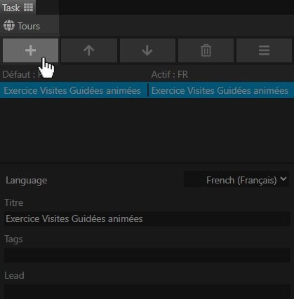
Create a new guided tour.
Open the Guided Tour parameters by clicking on the icon forming three horizontal bars, on the far right.
For this exercise, we will need to select the parameters:
-
Models to animate the change of object parameters (their visibility, material properties, etc.);
-
Slicers to allow the stator to be cut using the Cut Tool.
In the Parameters, select the Stator and make it visible again.
Remember to save your scene regularly, unless you are using standalone mode.
Next, we will create the first step of our guided tour. The creation of these steps is not always done in chronological order, but in the order in which it is most logical to create them. Therefore, it is advisable to rename your steps only at the very end, when they have finished being created and the tour’s composition is sure to be suitable.
This created step is a perfect example: the key, the pin-related mechanisms, etc… are already in position for an intermediate step.
For the purposes of this exercise, we will call it step A.
Before creating a new step, it is important to prepare the object parameters to prepare the animation of the Cut Tool.
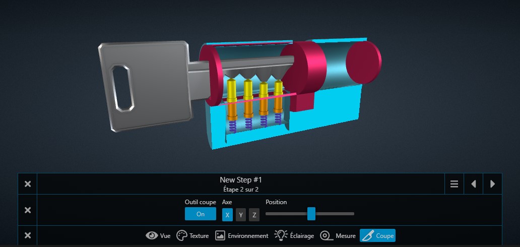
Animating the Cut Tool
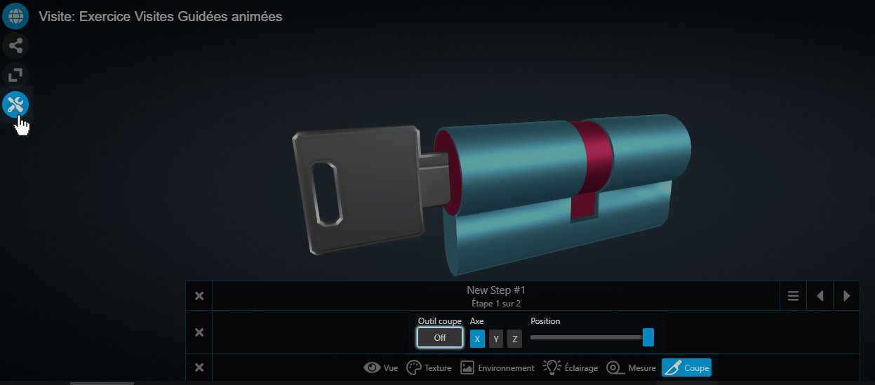
The stator is here represented as solid: it is therefore impossible to see the internal mechanism. In the Lock scene presented in the introduction of this page, the stator is present in the form of two distinct models: a solid stator, and a stator cut in half. The two objects alternate as needed via the Visible Options in the object parameters.
Here, we will use another method: with a single model, that of the solid stator, we will be able to obtain a stator cut in half via the Cut Tool.
During step 4, we activated the Slicer guided tour parameter, which allows the animation of this tool in guided tours. We can therefore indicate in the step which objects will be affected by this tool.
We will display the Scene Tools by clicking on the corresponding icon to the left of the Explorer. A tab will then open at the bottom of the Explorer.
By selecting the Cut Option, you will access the corresponding Tool.
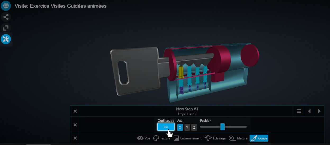
First, we activate the Cut Tool by clicking on the “Off” button to switch it to “On”. The X-axis is the default cutting axis selected, it is also the correct axis for this exercise. The slider labeled “Position” defines the state of the cut. Position it in the middle so that the stator is cut in half.
The rest of the objects are also affected by this Tool.
To remedy this, go to the Parameters tab.
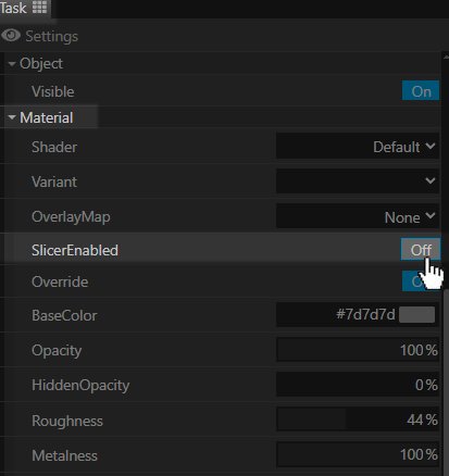
Deactivate the SlicerEnabled Option in the parameters of all objects, except the Stator.
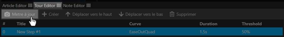
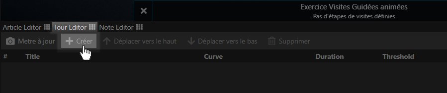
We will remember to update the step by clicking on the “Update” button in the Tour Editor at the bottom of the Explorer.
Why didn’t we set it up before?: the state of this option is set to On by default, and any change is only saved if the “Slicer” option is active in the guided tour parameters.
Why not set it up later?: New steps take the exact state of the scene and parameters at the time of their creation. If an option is active by default, it will be active in all steps. Changing a parameter would therefore mean updating all already created steps.
Finally, we can create a new step that will animate this cut.
Please ensure that the current Step presents the object in the desired position before creating the next step. Remember to Update the step if you wish to save any changes.
To do this, we will carefully select step 1 (which is currently the only one in the list) before clicking on the ”+ Create” icon.
We will name this step: Step B.
In this new step, we will be careful not to modify the scene’s viewpoint or its orientation so that the steps have strictly the same scale and orientation. This similarity will make the animations performed between the steps all the more attractive.
If you accidentally update a step by slightly moving the viewpoint, creating an unwanted offset between steps, you can delete the step, revert to a step with a good viewpoint, and recreate the step from there. Otherwise, if you have saved the scene in the meantime, and you have not saved the scene after this error, you can refresh the page to reset these changes.
This step will serve as an introduction to the guided tour. Currently, it is placed in the second position in the step list. To place it in the first place, click on the “Move up” icon.
Then deactivate the Cut Tool by clicking on the button to set it to “Off”.
Tip: to obtain a better transition effect between these two steps: place the “Position” slider all the way to the right. Remember to update the step to save these changes. You will notice that the cursor moves between the two steps: this is the Transition between steps which interpolates the states of the two steps. Note that this visually animates the cutting effect.
Animating the key
In the first step of the tour, where the stator is shown solid, we will move the key so that it is outside the stator.
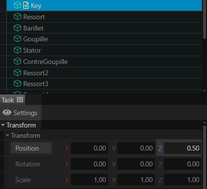
In the Key object’s parameters, we will adjust its Position Transform on the Z-Axis, setting it to 0.5.
Animating the key’s action on the cylinder
To animate the cylinder and pins, we will create the Step from Step 2, as the key and mechanisms are already in the correct position.
We will name this new step: Step C.
We will need to change the rotation of the key, the cylinder, and the four pins. These objects are driven by the same action, so they will consequently have the same rotation.
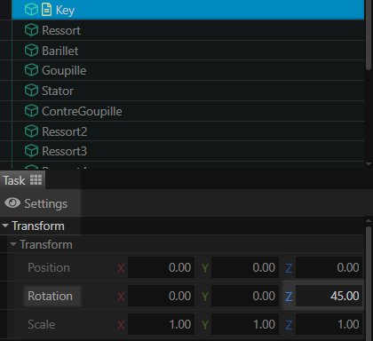
In the object Parameters, change the rotation of the Z-axis to a value of 45. Repeat this change for the objects mentioned just before.
Update the step and feel free to test the animations by clicking on the arrows to the right of the step tab.
Step 6: Refine your animations
From these three steps, you have managed to animate the functioning of a lock. Congratulations!
Nevertheless, the tour can be improved by adding transition steps, annotations, etc…
Animating the mechanism
We will create an additional step to show what the internal mechanism of the stator looks like when the key is not inserted. As it will serve as a transition between steps B and A. While it is entirely possible to start from step B to create it, we will use step A here, because it is important that the slicer cursor is identical between the two steps.
We will name this step: Step D.
Remember to move this step up to place it between steps B and A.
We start by moving the key so that it is outside the stator. To maintain a consistent transition, copy and paste the Transform values in the key’s Parameters from step B to the key in step D.
Still on step D, we will then proceed to animate the internal mechanism. Without the action of the key to push them, the springs are relaxed, and the pins and counter-pins are placed higher. It is important to keep in mind that the counter-pins block the mechanism in the absence of a key, so they must be placed at mid-height of the cylinder’s pin opening.
Here, we place:
- the Scale of the Springs on the Y-Axis at 1.5.
- the Position of the Pins and Counter-Pins on the Y-Axis at 0.03.
Update the step and check the animations.
Tip: it is sometimes difficult to correctly position mechanism parts if the view is too zoomed out. However, zooming in space is not good, as you risk modifying the viewpoint between different steps. It is still possible to check locations without fear: zoom in space, place a part in the correct position and note the new parameter values, change step and return to the desired step to reset the view. Change the object’s values according to the object, update the step, and repeat if necessary for other objects.
To go further: following the translation changes in step D, the mechanism animates when moving to step A… but also to step B, both sharing the same information given on these specific objects. The stator still being solid at the time of the transition between step B and D, this slight movement is not shocking. Nevertheless, it is possible to adjust this detail in two possible ways:
-
You can apply the changes from step D to step B, namely update the Position of the pins and counter-pins, as well as the scale of the springs;
-
Steps B and D only have one difference: the state of the Cut tool. You can therefore delete step B, create a new step from step D (to start again with a similar step), place it at the top of the list, and deactivate the Cut Tool.
The two methods described are optional and lead to the same result. The first is more reliable, as it does not require deletion or list changes in the Tour Editor. The second is faster, especially when it is necessary to modify many objects at once.
Adding Annotations
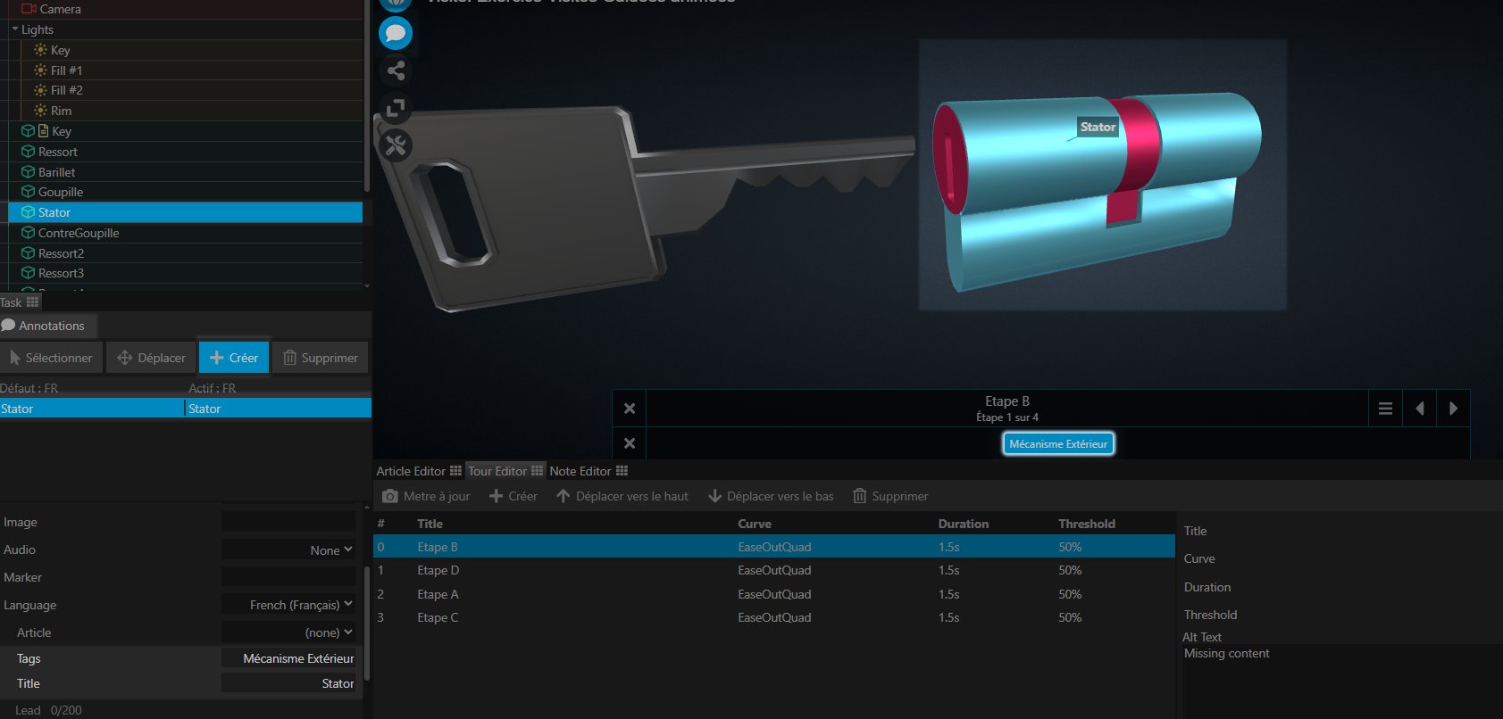
Here, we will see how to use annotation Tags to annotate the scene according to the guided tour steps. One part of the annotations will be displayed for the external mechanism (cylinder, stator, etc…), and the other part will be shown for the internal mechanism (pin, spring, etc…).
For the purposes of this exercise, we want to place the annotations at steps B and D. We start by selecting step B.

Go to the Annotation tab, at the top of the Explorer. We will start by creating annotations for the external mechanism.
First, select the Stator. For this exercise, only the annotation title and its tag will be changed. Feel free to go further if you wish: why not try setting your annotations to Extended and adding descriptions?
By clicking on the “Create” icon, then on the stator, an annotation is created. In its parameters, we change its title to “Stator”, and indicate its Tag as “External Mechanism”.
Repeat these actions for the Cylinder and the Bolt by adapting the Annotation Title according to the object. Caution: we remind you that annotations are linked to the objects in the scene: therefore, it is important to select the desired object before creating your annotation. For this exercise, it is important that these three objects share strictly the same Tag name.
Note: once the Tag is created, it will appear in the tags tab, below the Explorer. Remember to activate it to display it on the scene.
Now let’s move on to step D. We will do the same for one of the Springs, a Pin, and a Counter-Pin. This time, the Tag used must be different. Here, we will use the term “Internal Mechanism”.
Caution: if the internal mechanism is visible, remember that the stator still theoretically covers it. By trying to create an annotation on one of these internal parts, you will click on the stator, which is not desirable. Feel free to make the stator invisible in its object parameters while creating these annotations. Remember to make the stator visible again once the operation is complete.
Update the step, without forgetting to activate the newly created Tag. It is not necessary to create an annotation for each similar part, but you can, for example, alternate the annotated rows for better readability. (e.g., place an annotation on the pin of row 1, an annotation on the counter-pin of row 2, an annotation on the spring of row 3…).
Finally, let’s create an annotation for the key. For this part of the exercise, it is not necessary to create an annotation Tag for it. Without a tag, the annotation will be visible in both steps. You will notice that the bolt is in the same situation: you can remove its External Mechanism Tag by deleting this text in the Tags container of its parameters.
You can absolutely choose to keep the annotations displayed for the rest of the tour. You will also notice that the annotations follow the translations of the object to which they are attached. For readability, we advise you to only display the annotations for the External Mechanism Tag.
Performing an object change
For example, let’s assume you want to show the mechanism’s action with a wrong key. Naturally, you need two different key models.
It is therefore necessary to perform a model change at some point in the tour.
There are currently two methods to perform an object change in a DPO-Voyager scene. (In all cases, it requires importing a GLB with a unique name into the scene.)
Using Derivatives:
This method uses the Derivative function of Objects in the scene. An object can therefore contain several GLB models as a derivative.
During import, you just need to select the desired object (here the key) and choose a derivative other than High (the High object is the one that loads by default on the scene, so it is reserved only if you want to change the visual of the base object).
In the object’s parameters, you can then choose its derivative. (If you have imported the second key in the Medium derivative, you will notice that the object’s model changes between its High derivative and its Medium derivative).
This method has the advantage of lightening the list of objects in the scene, and making the whole thing more digestible. However, it can make the scene’s organization confusing. This method should therefore be reserved if your objects are related to each other, and have similar movements.
Here, the two keys have strictly similar demonstrations: it is therefore advantageous to use the Derivative system.
By importing a new object
This method is more classic. It consists of importing a new object into the scene and changing its visibility to Off or On depending on its appearance.
To go further
Now that you master the guided tour system, why not try to create a similar demonstration with a wrong key yourself?
Hint: You just need to duplicate the steps one by one (click on the step to duplicate and create a new step), then put them back in the correct order. Finally, change the key’s derivative and update the translations of the mechanisms (pins, counter-pins, and springs) to match its different shape.