Learning to use the Tools and settings of a DPO-Voyager scene
Not to be confused with the scene editing settings, the tools and settings form a set of features available to the user both in editing mode and in viewing mode.
With them, you can, among other things, change the camera’s point of view (switch from a perspective to an orthographic view), modify the scene’s lighting, slice the model along an axis, or measure it with a ruler tool.
Summary
Understanding what a scene’s tools and settings are
These non-destructive tools are used to quickly change a scene’s display settings, such as the camera’s point of view (switching from a perspective to an orthographic viewpoint), the environment, or the lighting.
They have the advantage of being easily accessible, while also offering the possibility of being staged during a guided tour. Be aware that not all features can be animated in a guided tour. These specifics are noted for each function in the tools listed below.
Generally speaking, most of the functions found in these settings can also be found in the scene settings within DPO-Voyager’s editing mode.
-
Changing the scene settings in DPO-Voyager editing mode and saving those changes will modify the default display of your scene.
-
Changing the scene display settings from the settings icon will not change the default display values of your scene. The changes will therefore be local and will be replaced by the default values as soon as the page is refreshed in your browser.
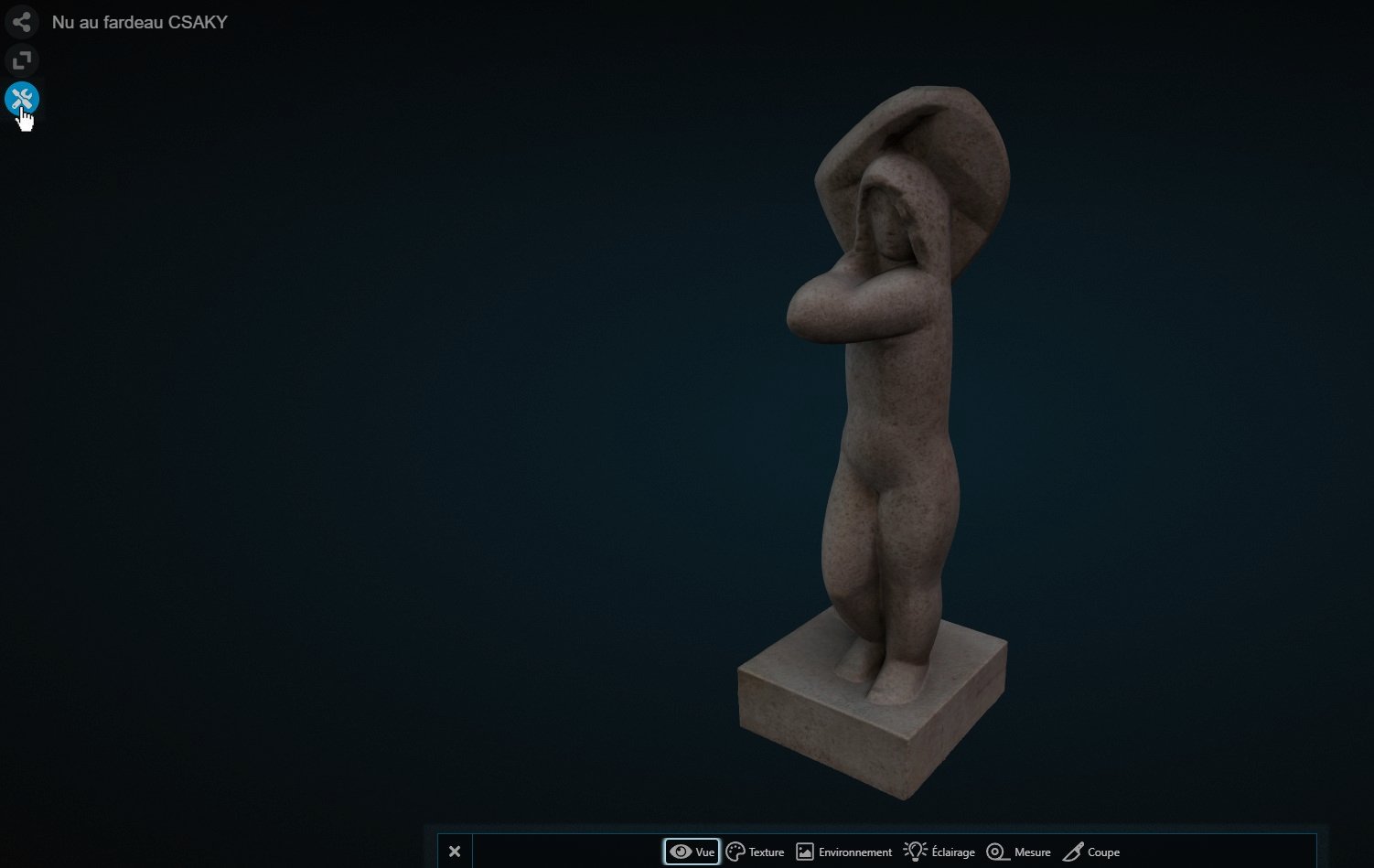
To bring up these tools, simply click the corresponding icon on the left side of the Explorer.
The View tool
| Function | Sub-function | Description | Animatable in Guided Tours |
|---|---|---|---|
| Projection | Perspective | Reproduces the human eye’s point of view: distant objects appear smaller | No |
| Orthographic | No notion of depth, objects are seen at the same scale | No | |
| View | Front | Reorients the point of view to the front of the scene | No |
| Back | Reorients the point of view to the back of the scene | No | |
| Left | Reorients the point of view to the left of the scene | No | |
| Right | Reorients the point of view to the right of the scene | No | |
| Top | Reorients the point of view above the scene | No | |
| Bottom | Reorients the point of view below the scene | No |
Note the points of view are fixed relative to the scene. If your object does not appear at the correct angle when you select a specific view, it means the object is poorly oriented relative to the scene.
To reorient the object, please go to the Pose tab at the top of the Explorer. To learn more, you can consult this guide.
Creating an orthophoto with the View tool
You can create orthophotos with a DPO-Voyager scene using the View tool described above.

To do this, enable the toolbar in the scene Editing mode. Then go to the settings of the View tool.

By default, the projection is set to Perspective. Click on Orthographic right next to the Perspective button.
Once in orthographic projection, select the desired view (from the 5 available).
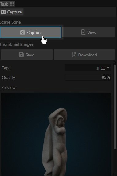
Then go to the “Capture” tab at the top of the Explorer. Click “Capture” to take a screenshot of the desired orthographic view.
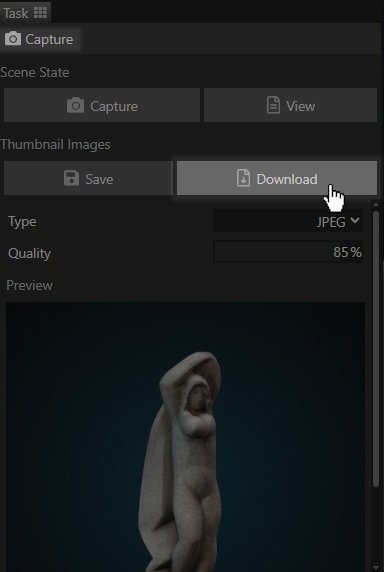
Once the screenshot is taken, a preview will appear at the bottom of the tab. If the resulting image does not suit you, repeat the process until you obtain the desired photo.
Once satisfied with your capture, click the “Download” button to download the resulting image.
Be careful: it is not necessary to click “Save” during this process. This operation is only useful if you want the screenshot to become the thumbnail of your scene.
The Texture tool

| Function | Sub-function | Description | Animatable in Guided Tours |
|---|---|---|---|
| Texture | Default | Displays your object according to the display settings of its source file | Yes |
| Clay | Displays your object with a rendering that mimics the visual properties of clay | Yes | |
| X-ray | Displays your object as transparent, mimicking a “ghostly” look | Yes | |
| Normals | Displays your object by coloring it according to how light interacts with it (see advanced guide) | Yes | |
| Wireframe | Displays your object as transparent, only the model’s 3D mesh is visible | Yes |
Be aware that Materials can only be animated through the Texture tool. An object’s “Shader” setting, which fulfills a function similar to the Texture tool, cannot be animated.
Default material
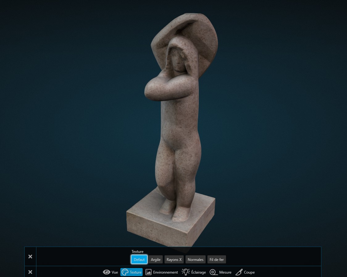
Displays the scene’s 3D models with the same material information as the source .glb files.
It is the only material in the list that displays so-called “Albedo” texture information.
Clay material
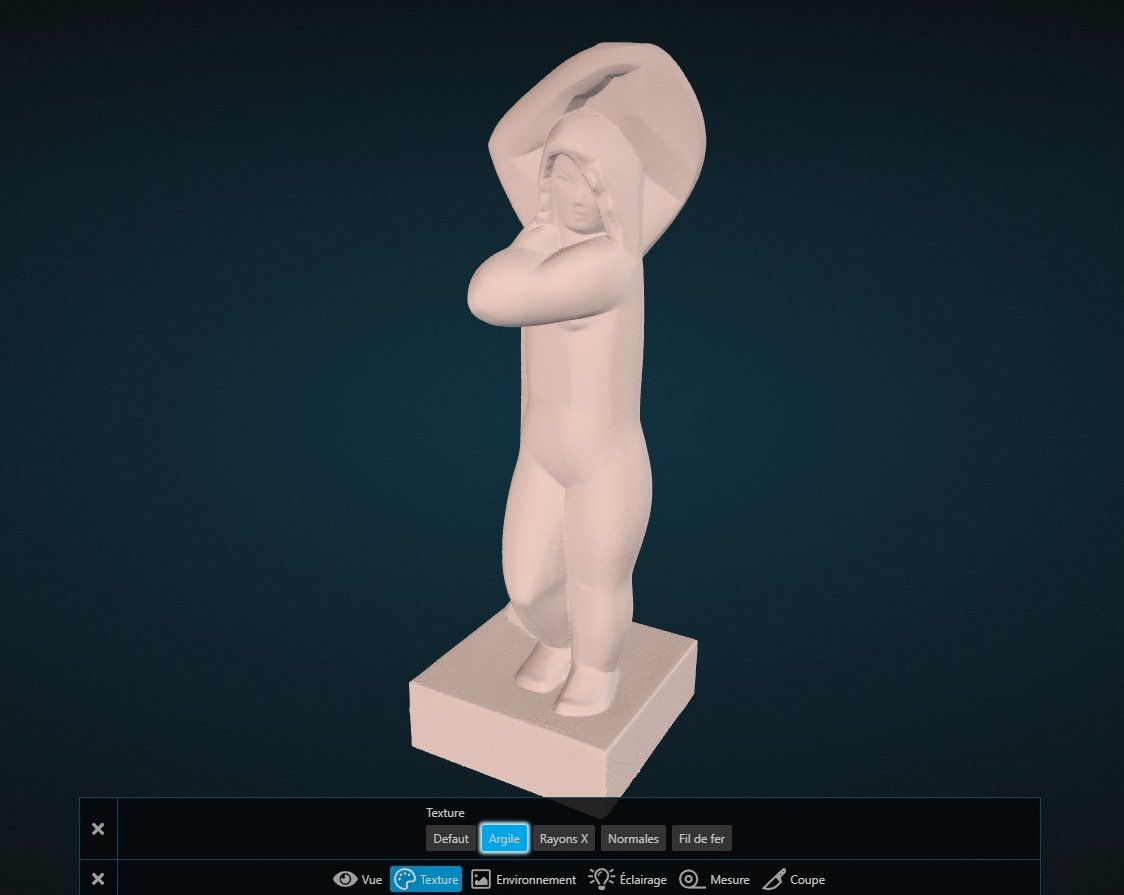
Displays the scene’s 3D models with a material that mimics the visual properties of clay.
Widely used in 3D sculpture, this material makes it possible to assess the quality of the model’s surface.
An object’s Albedo texture can sometimes be misleading. It is said to “fake”, to mimic volume information that the model does not actually incorporate.
Its absence therefore makes it possible to appreciate the proper definition of the volumes and their true interaction with the scene’s lights.
X-ray material
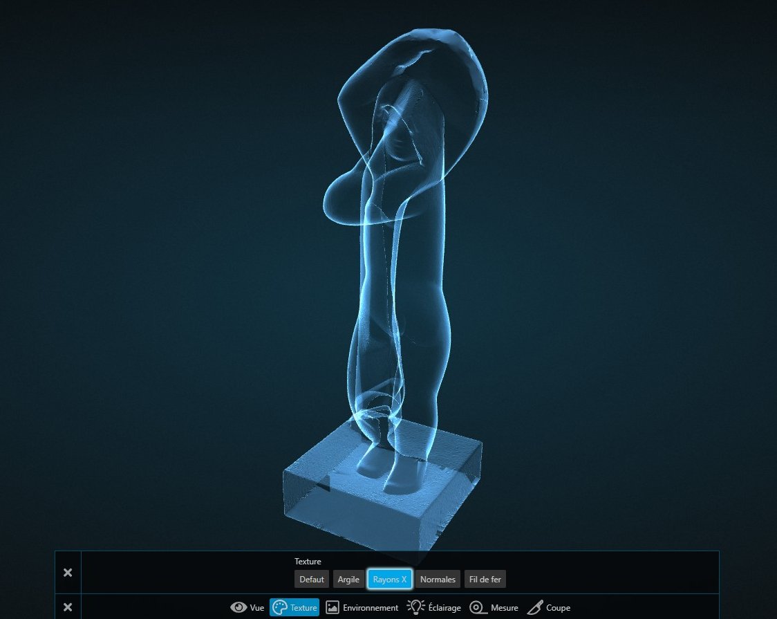
Displays the scene’s 3D models with a semi-transparent material, mimicking a “ghostly” visual appearance.
It is mainly useful for staging aspects of Guided Tours, to represent a scanner effect, for example.
Normal material
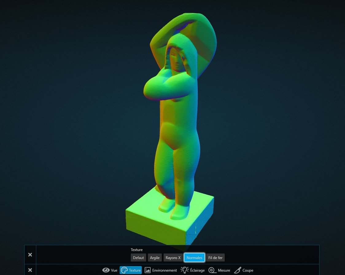
Displays the scene’s 3D models with a material that shows the normals in a visual form.
This material is useful for checking that a Normal Map is properly present in your objects. As a reminder, a Normal Map makes it possible to artificially add surface micro-details without touching the object’s geometry. If you wish, you can learn more by following this guide.
Wireframe material
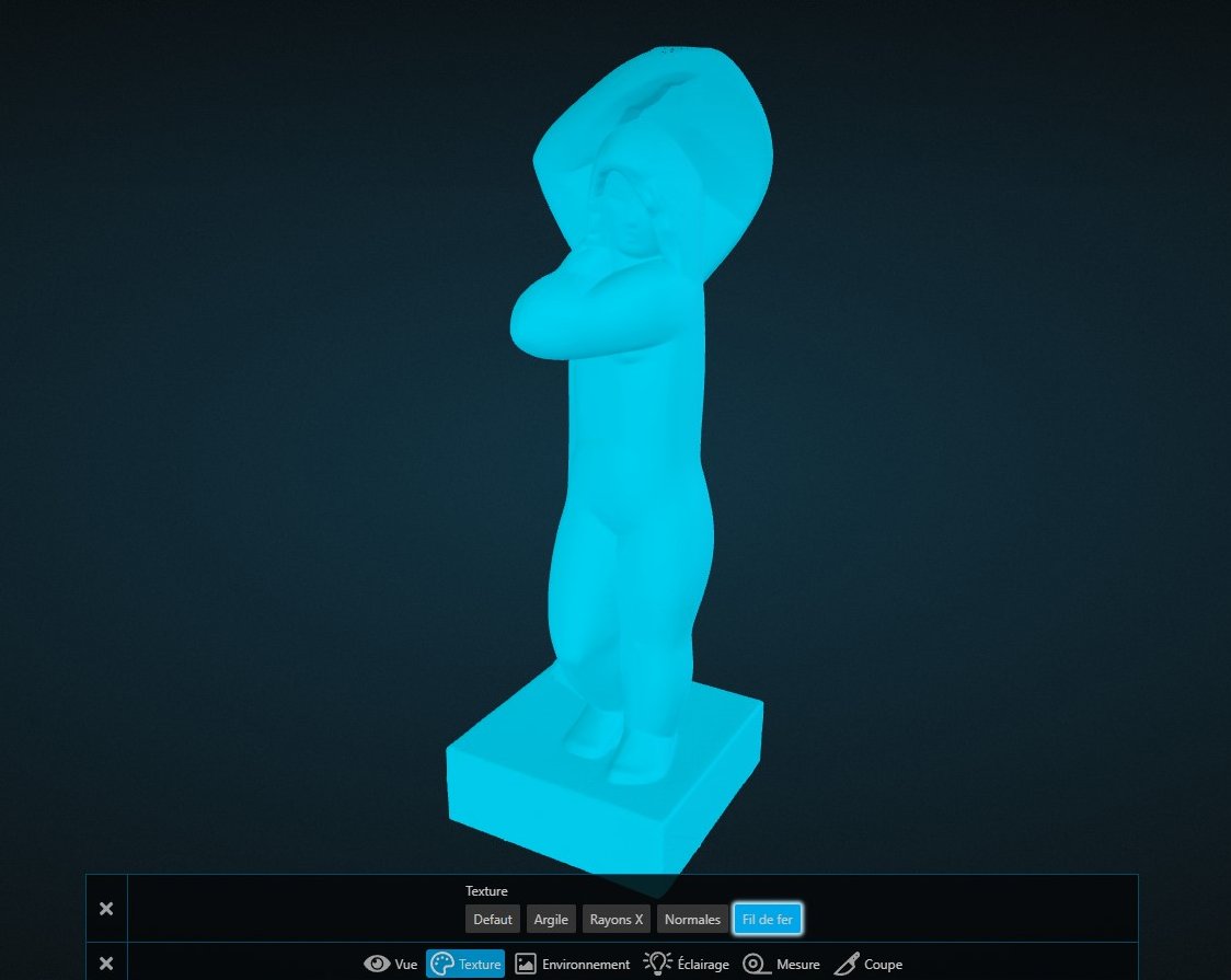
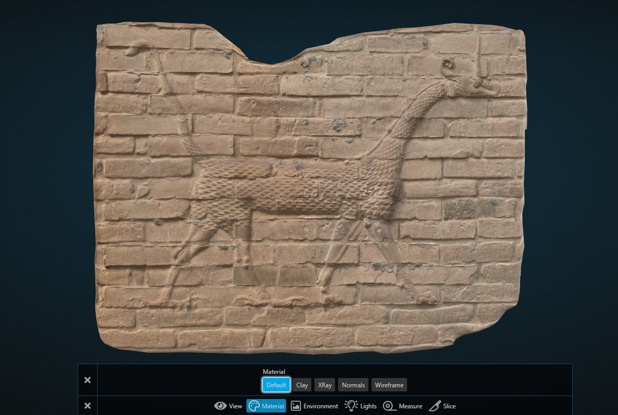
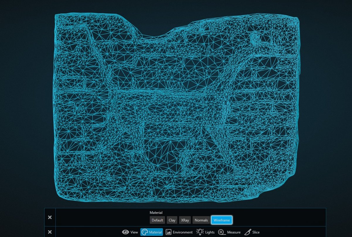
Displays the scene’s 3D models with a transparent material, showing only the edges and vertices of the 3D meshes.
Be careful: since this material is based on your 3D model’s mesh, it may not have the expected effect if your object’s mesh is too dense.
In the example of the Nu au Fardeau, the object’s mesh is so dense that the Wireframe material gives it a solid appearance. You have to zoom in more than reasonably to see the edges and vertices appear.
For comparison, here is how the Wireframe material behaves with another model, with a lighter mesh:
The Environment tool

This tool focuses mainly on the scene’s environment, that is, the space surrounding the imported models.
It therefore serves to showcase them properly, and can be modified to match established graphic charters.
| Function | Sub-function | Description | Animatable in Guided Tours |
|---|---|---|---|
| Background | Solid | Colors the background with a solid color. Only color 1 is used for this change | No |
| Linear | Colors the background with a horizontal gradient. Color 1 is at the bottom, color 2 is at the top. | No | |
| Radial | Colors the background with a radial gradient. Color 1 is at the center, color 2 is on the outside | No | |
| Color 1 | Allows you to change the primary background color | Yes - Option: Background | |
| Color 2 | Allows you to change the secondary background color | Yes - Option: Background | |
| Grid | Grid | Displays a grid as the scene’s floor. The square to its right represents its color setting | No |
| Floor | Floor | Displays a radial gradient as the scene’s floor. The square to its right represents its color setting | No |
| Env Map | Env Map | Allows you to change the scene’s Environment Map. It determines the metallic reflections adopted by objects with a Metallic value greater than 0 | No |
The Lighting tool

As its name suggests, this tool allows you to modify the lighting settings present in the scene. By default, a Voyager scene includes 4 lights, based on the principles of photo studio lighting, described below.
Note the lights follow the camera’s movements. For example, the secondary light oriented to the left will always illuminate the left of the Explorer, regardless of whether you are viewing the front or the back of the object.
| Function | Sub-function | Description | Animatable in Guided Tours |
|---|---|---|---|
| Lighting | Main | Allows you to adjust the intensity and color of the scene’s main light | Yes - Option: Lights |
| Fill 1 | Allows you to adjust the intensity and color of the right-oriented secondary light of the scene | Yes - Option: Lights | |
| Fill 2 | Allows you to adjust the intensity and color of the left-oriented secondary light of the scene | Yes - Option: Lights | |
| Backlight | Allows you to adjust the intensity and color of the scene’s Rim light | Yes - Option: Lights |
Main lighting
The Main light, also called the Key Light, is the most important in the scene. It is the one that emits the most light. It is always placed in front of the camera.
Generally, its color is white, so as not to influence the actual color of the illuminated object. A main light can be colored to give the scene specific moods (e.g., blue to recreate a day-for-night effect).
Secondary lighting
The Secondary light, also called the Fill Light, is an optional but favored light. It is traditionally placed toward the front of the subject, oriented to the left or the right.
Their role is to complement the area of light emitted by the main light. They are often slightly colored to create softer, more interesting shadows in photography.
Here, DPO-Voyager scenes are by default composed of two secondary lights. Fill #1 is oriented to the right of the screen, whereas Fill #2 is oriented to the left of the screen.
It is customary to use warm colors for these lights, or to alternate a warm color on one side and a cool color on the other.
Backlighting
The Backlight, also called the Rim Light, is the most optional of all the lights presented. Traditionally placed behind the subject, they serve to create a halo of light on its contours in order to showcase it.
In the scene, the backlight is placed in the background, to the right of the screen.
It is customary for this light to be colored so as not to contradict the Main Light. Cool colors are favored, to contrast with the generally warm colors of the Secondary Lights.
The Measurement tool

The measurement tool allows you to measure the distance between two points selected in the scene. How it works is described below.
| Function | Sub-function | Description | Animatable in Guided Tours |
|---|---|---|---|
| Measurement | Activation | Enables the ability to measure a distance between two points defined by the user | No |
To use this tool, first select it from the list of Tool settings.
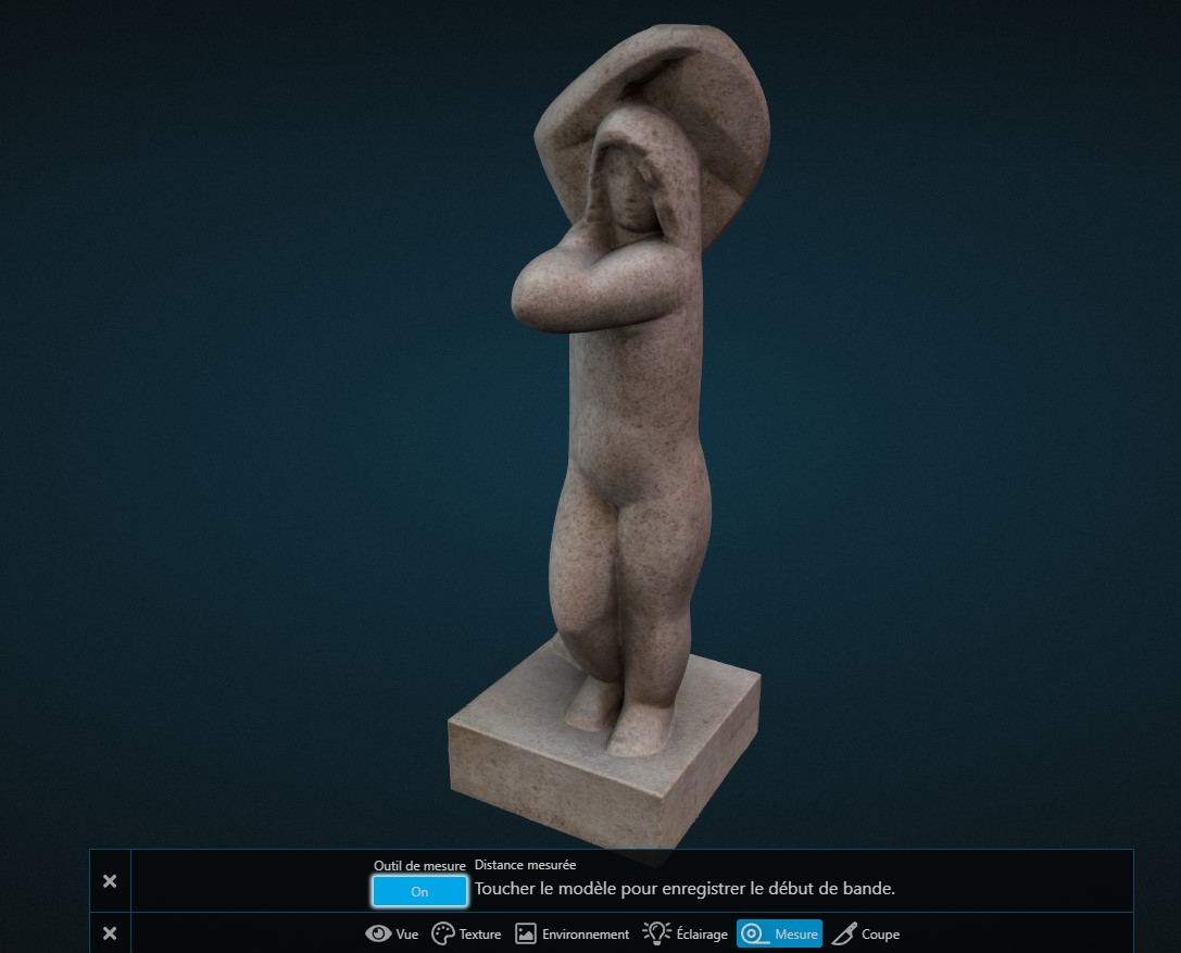
Then, click the “Off” button to switch it to “On”.
As long as the Measurement tool is active, you will be able to click on any part of the scene, as long as you land on a visible 3D model.
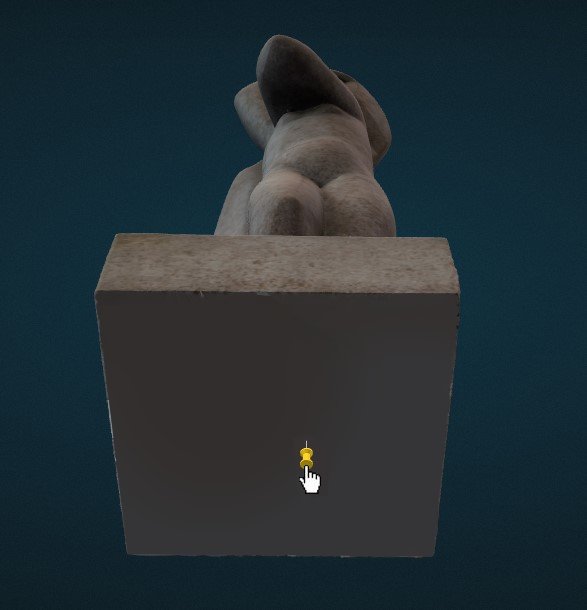
The first click will place a first point in the form of a pin.
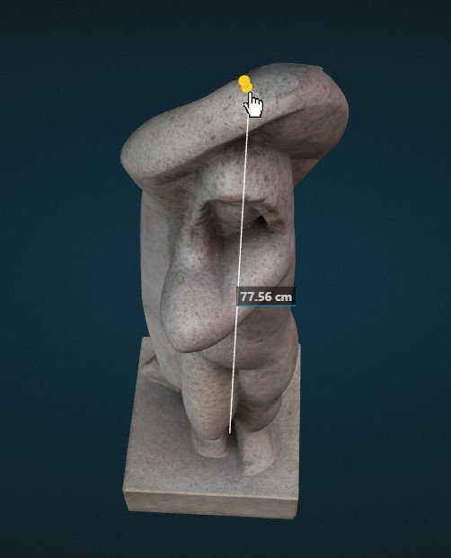
Following the same logic, the second click will place a second point, which will cause a line to appear between the first and last point.
For now, there cannot be more than one distance displayed. A third click will erase the previous points and create a new one.
The units of measurement displayed by the distance are tied to the scene’s Global Unit setting.
Changing a scene’s units of measurement
To change this unit of measurement, go to the “Pose” tab at the top of the Explorer. Then select a model in the Navigator on the left side of the Explorer.
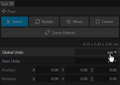
A tab will then appear at the bottom left of the Explorer. Click the arrow in the container of the Global Units setting.
The Slice tool
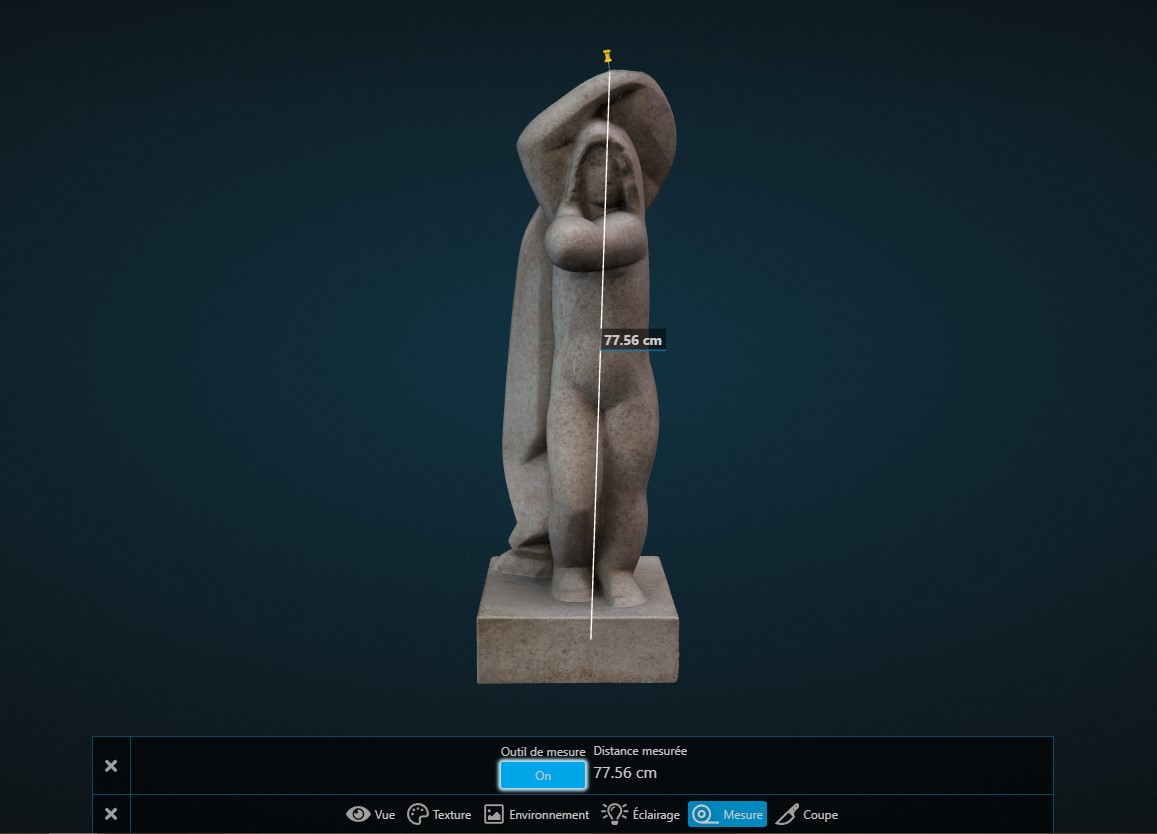
Last on the list, but by no means least, the Slice tool allows you to section a 3D model along a given axis. One part of the model remains intact while the other disappears. The hole in the model created by the slice is filled in and automatically colored blue.
As a reminder: these settings are non-destructive. Using the Slice tool will not affect your 3D file’s mesh, only its display. You can therefore use the Slice tool without fear of altering your source model.
| Function | Sub-function | Description | Animatable in Guided Tours |
|---|---|---|---|
| Slice Tool | Slice Tool | Enables the activation of the Tool. One of the three axes will always be selected by default | Yes - Option: Slicer |
| Axis | X | Slices your models along their width | Yes - Option: Slicer |
| Y | Slices your models along their height | Yes - Option: Slicer | |
| Z | Slices your models along their depth | Yes - Option: Slicer |
Note: you can reverse the direction of the slice by clicking again on the desired axis.
Important You can choose which object is affected by this tool or not. This choice is made in the object’s settings under the Material category: SlicerEnabled.
The X Axis
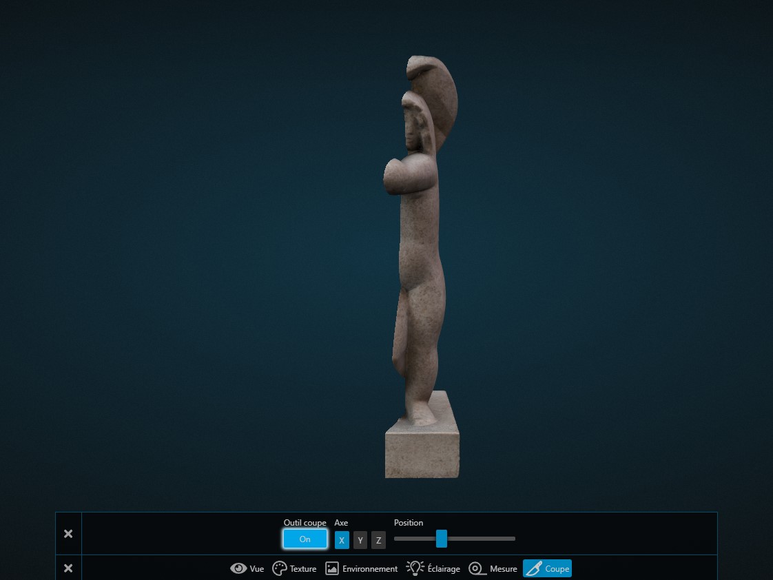
Assuming the object is placed in the same orientation as the scene: slices the object along an X axis, representing here the length (left/right).
Note: you can reverse the direction of the slice by clicking again on the desired axis.
The Y Axis
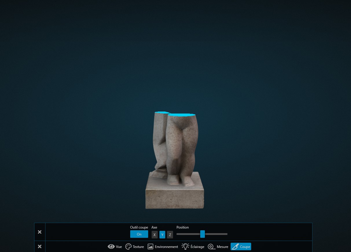
Assuming the object is placed in the same orientation as the scene: slices the object along a Y axis, representing here the height (top/bottom).
Note: you can reverse the direction of the slice by clicking again on the desired axis.
The Z Axis
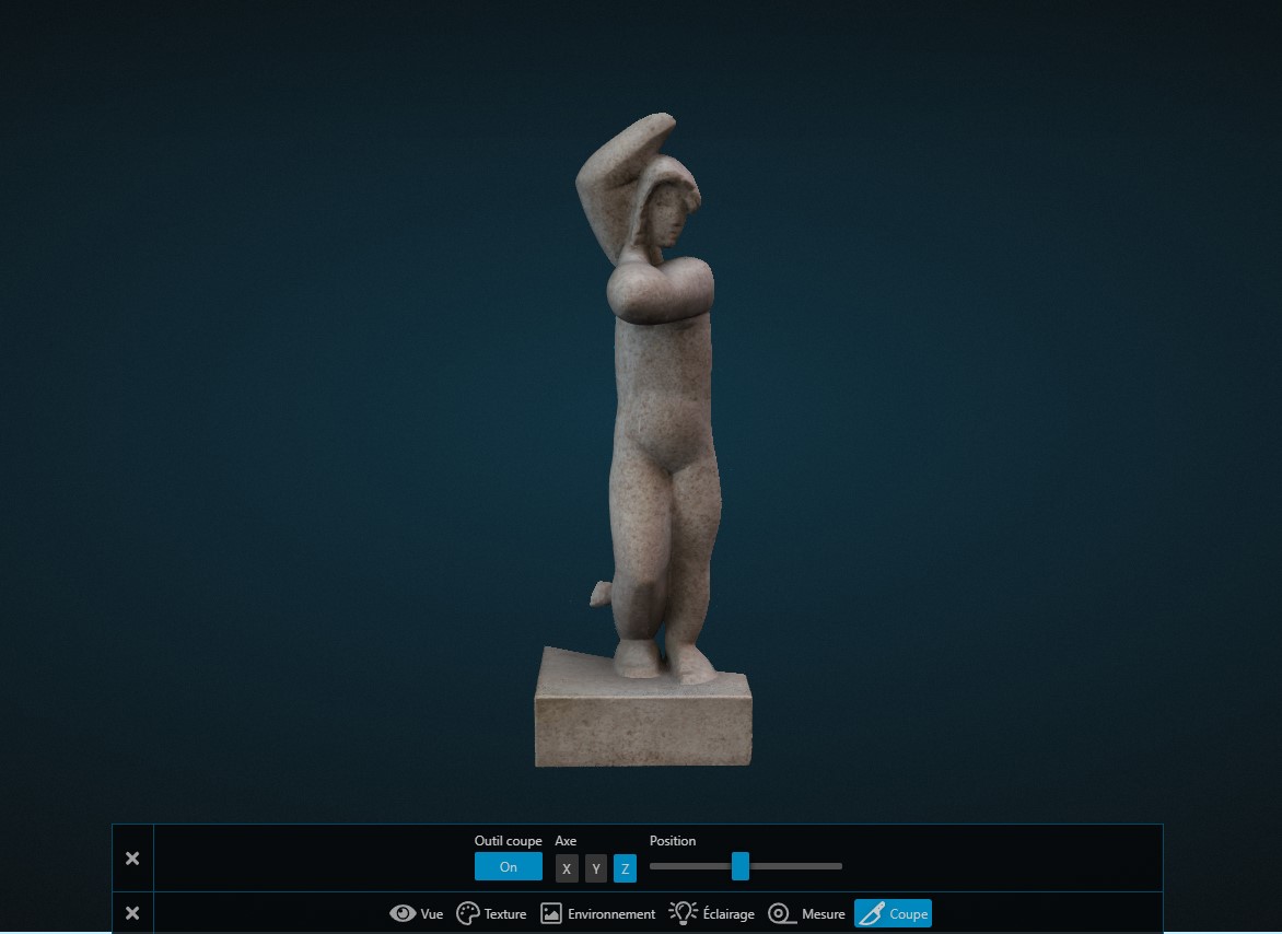
Assuming the object is placed in the same orientation as the scene: slices the object along a Z axis, representing here the depth (front/back).
Note: you can reverse the direction of the slice by clicking again on the desired axis.